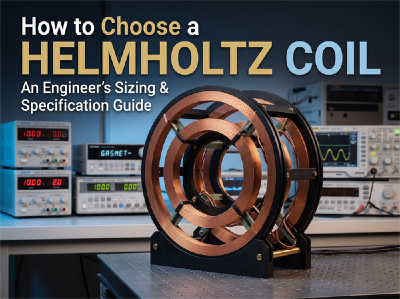
A Helmholtz coil generates a highly uniform magnetic field within a defined central volume by pairing two identical coaxial coils separated by an axial distance equal to their radius (d=R).
In practice, specifying the wrong coil diameter or driver matching leads to thermal runaway, clipped drive voltages at high frequencies, or field gradients that invalidate sensor calibration.
Selecting a coil system involves working through eight engineering considerations, ordered from physical boundaries to electrical integration.
1. Uniform Volume vs. Coil Radius (R)
The central field uniformity governs the required physical size of the coil. A common design pitfall is sizing the coil to match the physical boundary of the Device Under Test (DUT).
For a circular Helmholtz pair with radius R, the field varies as a function of displacement from the geometric center (x=0,y=0,z=0):
±1% Uniformity: The usable test volume is roughly a sphere of diameter 0.4×R.
±0.1% Uniformity: The usable test volume shrinks to a sphere of diameter 0.2×R.
Example: If your DUT or sensor jig spans 100 mm in all directions and requires ≤ 0.5% field deviation across its entire volume: Minimum Radius (R) ≈ 100 mm / 0.3 ≈ 333 mm (Coil Diameter ≥ 667 mm)
If testing requires uniform fields across bulky assemblies, Merritt 4-coil systems or square Helmholtz coils offer wider uniform areas for a given cross-sectional footprint, though at higher construction and driver complexity.
2. Center Field vs. Current Sizing (B0)
The magnetic flux density B0 at the midpoint along the central axis is given by:
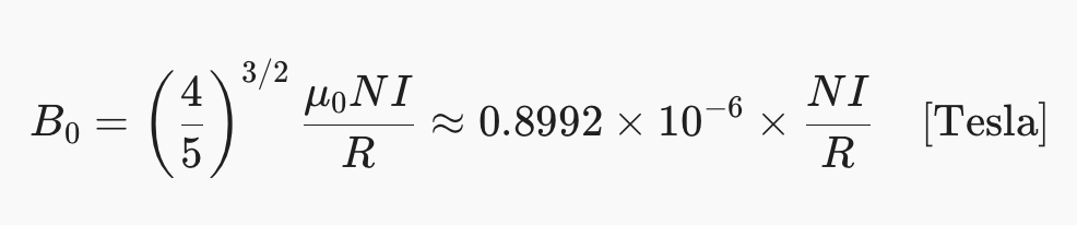
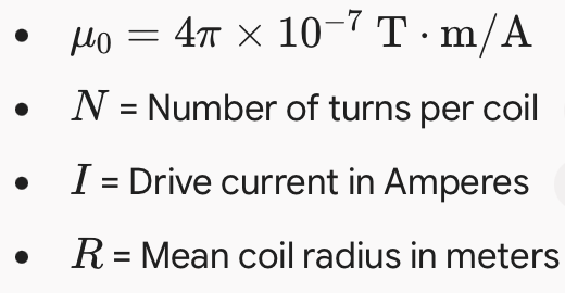
Where:
The metric to request from a vendor is the Coil Constant (expressed in μT/A, G/A, or mT/A).
To increase field: Increase turns N or current I.
The trade-off: Increasing N raises resistance Rdc (generating heat) and inductance L (limiting AC bandwidth).
3. Operating Frequency & Driver Matching: DC vs. AC
A coil optimized for DC calibration will frequently fail or overheat if driven at 10 kHz. Specify your operating regime early:
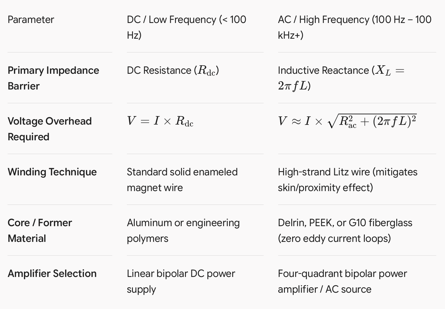
The AC Inductive Voltage Trap
At high frequencies, inductive reactance dominates. For example, a 2 mH coil pair running at 20 kHz exhibits an impedance of:

Driving just 2 A through this pair requires an output voltage swing of:

To drive substantial fields at high frequencies, verify whether you require an internal/external tuning capacitor network (series resonance) to cancel out XL at designated test frequencies.
4. Single-Axis vs. 3-Axis Orthogonal Systems
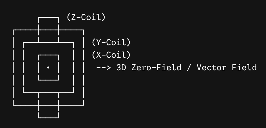
Single-Axis: Suitable for unidirectional sensor verification (Hall probes, reed switches, fluxgates) and simple magnetic susceptibility tests.
3-Axis (Triaxial): Necessary for:
Earth's field cancellation: Generating a true zero-field environment (< 10 nT) by nullifying background geomagnetic vectors (Bx,By,Bz).
Attitude determination simulation: Testing aerospace magnetometers, cubesats, and inertial measurement units (IMUs) under rotating vector fields.
Engineering Note for 3-Axis Units: Coils must be concentric and nested. Because outer coils have larger radii than inner coils, their turns and spacing must be independently scaled to maintain matched coil constants and uniform test zones.
5. Structural and Material Considerations
Any conductive or ferromagnetic material near the uniform volume will distort field geometry and introduce measurement artifacts:
Non-Magnetic Assembly: Fasteners and structural plates must be 316 stainless steel, brass, titanium, or non-metallic nylon/PEEK. Standard 304 stainless steel can work-harden and become weakly ferromagnetic under machining stress.
Eddy Current Prevention (AC Systems): Avoid solid metal bobbins in AC applications. Alternating fields induce eddy currents inside metallic structural rings, resulting in opposing magnetic fields and heavy phase shifts. Use slotted aluminum frames or non-conductive composite structures (G10/FR4, POM).
6. Thermal Dissipation and Duty Cycle
A coil running at 10 A through a 3 Ω winding dissipates:

Unless cooled, copper resistance increases predictably by:
 As the winding heats up, its resistance rises, reducing the current and field output if powered by a constant-voltage supply.
Continuous Operation (100% Duty Cycle): Ensure the selected wire gauge maintains current density below 3.0–3.5 A/mm2 under natural convection, or specify active water/air cooling.
Short-Burst Testing: If your test protocol requires high pulsed fields (e.g., 5 seconds on, 60 seconds off), request custom winding profiles rated for short-duration duty cycles to avoid oversized coils.
7. Field Verification and Calibration Standards
Reputable coil manufacturers validate and map the field profile prior to shipment rather than relying purely on theoretical models. When requesting quotes, verify what calibration data is included:
Center Field Calibration: Measured with an NMR teslameter (for high precision) or a calibrated 3-axis fluxgate/Hall probe.
Volumetric Uniformity Mapping: A 3D scan plot along the X, Y, and Z axes demonstrating compliance with the targeted tolerance (±0.1% to ±1%) over the required displacement.
Traceability: Calibration certificates traceable to NIST, PTB, or equivalent national metrology institutes.
8. Specification Checklist for RFQs
Before contacting manufacturers, compile your technical requirements using this checklist:
[ ] Uniform Test Volume: Diameter ____ mm (Spherical / Cylindrical)
[ ] Required Uniformity: ±____% over the defined volume
[ ] Target Field Strength (B₀): ____ mT (or Gauss / A/m)
[ ] Operating Mode: [ ] Pure DC [ ] AC Sweep [ ] Pulsed
[ ] AC Frequency Range: ____ Hz to ____ kHz
[ ] Number of Axes: [ ] 1-Axis [ ] 2-Axis [ ] 3-Axis [ ] Mechanical Constraints: Max outer footprint ____ mm; Clear central bore ____ mm
[ ] DUT Environment: Non-magnetic mounting shelf required? [ ] Yes [ ] No [ ]
Power System: [ ] Coil pair only [ ] Turnkey system (including bipolar power supply + Gaussmeter)